
Cisco Meraki
Connect a Sign-In Context to Cisco Meraki. Pick a Meraki Deployment Type (MAC-based Access Control, optionally with a managed pre-shared key, or Splash Page via RADIUS Server), then mirror the exact Meraki-Dashboard steps shown inline in the Netgraph admin.
The Cisco Meraki integration lets the Sign In Captive Portal work on Meraki wireless networks without any additional hardware. The two sides meet over RADIUS: Netgraph is the RADIUS server, Meraki is the client. How the two are wired together depends on the Meraki Deployment Type you pick on the Context:
- MAC-based Access Control (MAB) — Meraki performs MAC authentication against Netgraph’s RADIUS service, and the guest lands on a Cisco ISE-style splash page. Optionally, you can layer a Managed Pre-Shared Key on top so the SSID is encrypted with a venue-wide PSK.
- Splash Page via RADIUS Server (CoA) — Meraki uses “Sign-on with my RADIUS server”, a Custom Splash URL that points at Netgraph, and (optionally) the Meraki Location and Scanning Integration.
In both deployment types Meraki authenticates against Netgraph's RADIUS service with a splash page in front of the guest: plain RADIUS, with Change of Authorization (CoA) in the Splash Page deployment. No on-site gateway is required.
Configure everything under Service Integration → Meraki in the Sign-In Context admin.
Prerequisites
Section titled “Prerequisites”- A Cisco Meraki organisation with admin access to the Meraki Network you want Sign In to serve, and at least one SSID available for guest traffic.
- MR-series Access Points (and Meraki MX security appliances for CoA deployments that include them).
- The Sign-In Context’s Network Integration includes Cisco Meraki (chosen at Context creation or under Network Settings afterwards).
1. Enable the Meraki integration
Section titled “1. Enable the Meraki integration”Open Service Integration → Enabled integrations in the Sign-In Context admin and turn on Meraki Integration Enabled. Save with Update Settings. A new Meraki entry appears in the left nav with Settings and Access Points under it.
Note
If only Meraki integration is used on this Context, leave Service Gateway Enabled off.
2. Pick a Meraki Deployment Type
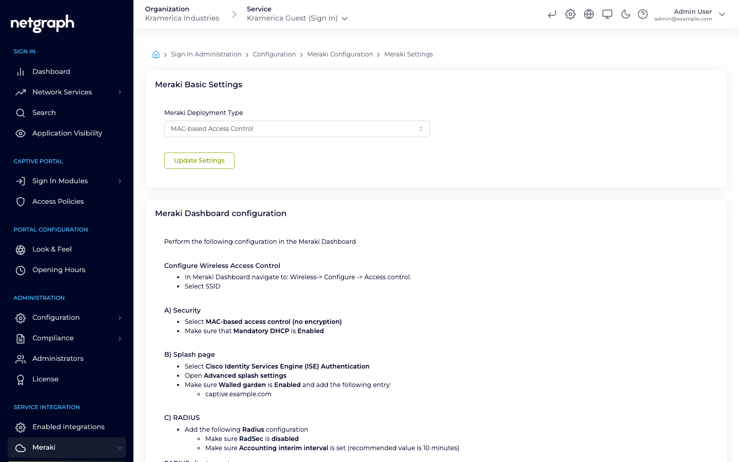
Section titled “2. Pick a Meraki Deployment Type”Open Service Integration → Meraki → Settings. The Meraki Basic Settings card has one dropdown:
- MAC-based Access Control — the MAB flow. Cards below the dropdown show the Meraki-Dashboard steps for this deployment and an optional Managed Pre-Shared Key card.
- Splash Page via RADIUS Server — the CoA flow. A second dropdown (Meraki CoA setup) asks whether the venue has Only Meraki AP, Only Meraki MX, or a Mixed Deployment (both AP and MX).
Save with Update Settings. The cards below change to match.
3a. MAB — MAC-based Access Control
Section titled “3a. MAB — MAC-based Access Control”The MAB flow is the shorter path: Meraki does MAC authentication against Netgraph’s RADIUS service and the guest lands on an ISE Authentication splash page. The Netgraph admin shows you exactly what to configure in the Meraki Dashboard — mirror each value from the Meraki Dashboard configuration card on the right.
In the Netgraph admin
Section titled “In the Netgraph admin”-
Pick MAC-based Access Control
Under Meraki Basic Settings, pick MAC-based Access Control and save.
-
Set the RADIUS client secret
In the Meraki Dashboard configuration card, enter a strong RADIUS client secret and click Update RADIUS client secret. This is the shared credential Meraki will use to reach Netgraph.
-
Read the generated values
The same card now shows the RADIUS servers and RADIUS accounting servers tables (host, port, secret per row) and a walled-garden entry. Keep these in view — you’ll paste each into the Meraki Dashboard next.
In the Meraki Dashboard
Section titled “In the Meraki Dashboard”Navigate to Wireless → Configure → Access control and pick the guest SSID, then:
-
Security
Set Security to MAC-based access control (no encryption). Ensure Mandatory DHCP is Enabled.
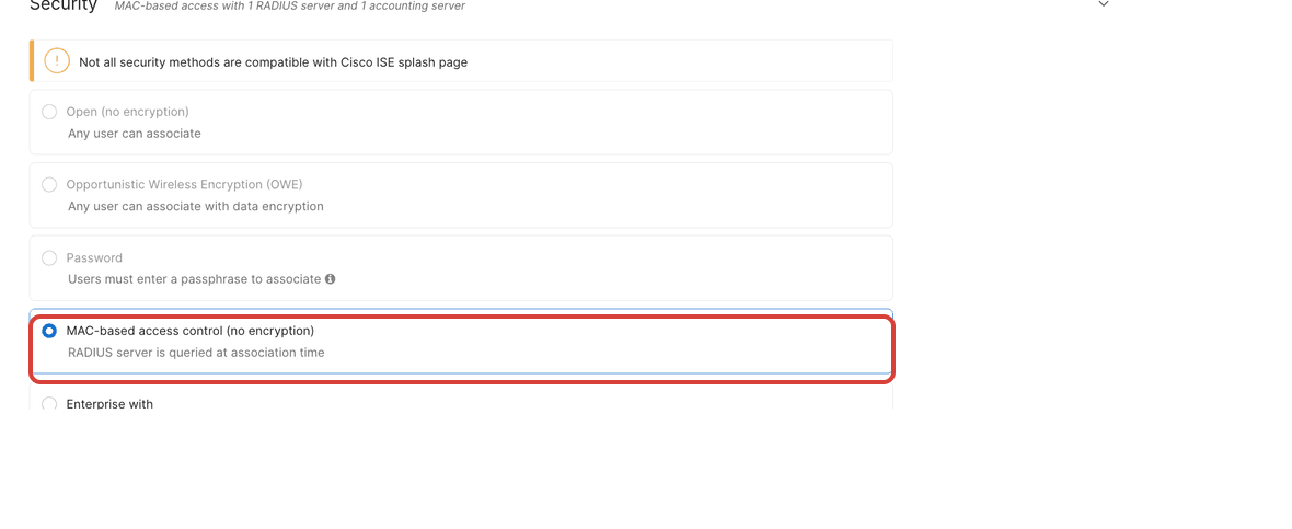
Set Security to MAC-based access control (no encryption). 
Set Mandatory DHCP to Enabled. -
Splash page
Set Splash page to Cisco Identity Services Engine (ISE) Authentication.
Netgraph uses the same implementation as Cisco ISE to handle the authentication.
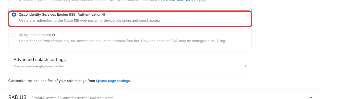
Set Splash page to Cisco Identity Services Engine (ISE) Authentication. -
Walled garden
Open Advanced splash settings, enable Walled garden, and add the domain shown in the Netgraph admin. Select Block all access until sign-on is complete.
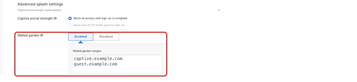
Enable the Walled garden and add the captive portal ranges from the settings page. -
RADIUS and RADIUS accounting
Under RADIUS, add each row from the Netgraph admin’s RADIUS servers and RADIUS accounting servers tables — host, port, and secret. Ensure RadSec is disabled, and set an Accounting interim interval (Netgraph recommends ~10 minutes).
Tip
If the Accounting Server row is not visible on the Meraki Access Control page, contact Meraki support to enable it on the Organization.
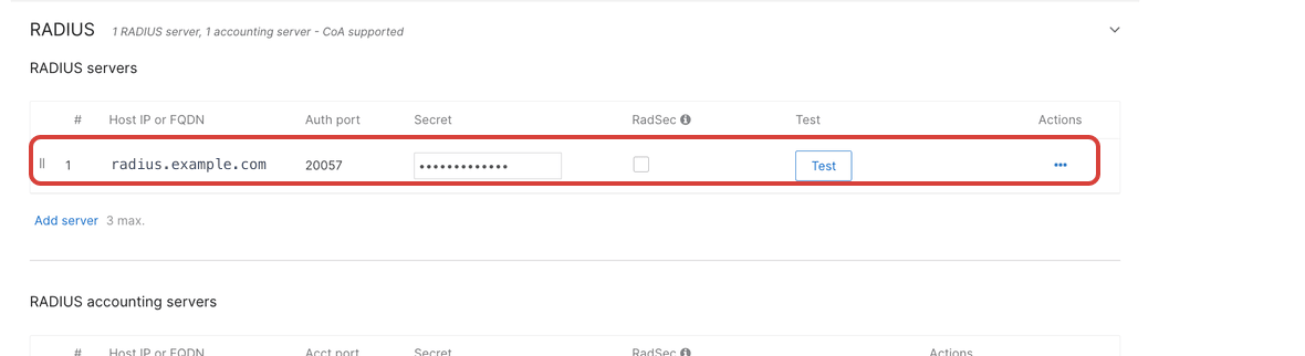
Add the platform as the RADIUS server: host, port, and the shared secret from the settings page. 
Fill in the RADIUS accounting server too: same host, accounting port, and secret. -
Device profiling
Enable RADIUS Accounting Device Profiling support. Meraki then includes device-profiling information in the RADIUS Accounting-Request messages it sends to the accounting server, which Sign In uses to recognise and classify connected devices.

Enable RADIUS Accounting Device Profiling support. -
Called-station-ID
Under Advanced RADIUS settings, add AP Name to the Called-station-ID category list. Sign In uses this value to identify which Access Point a guest is connected to.
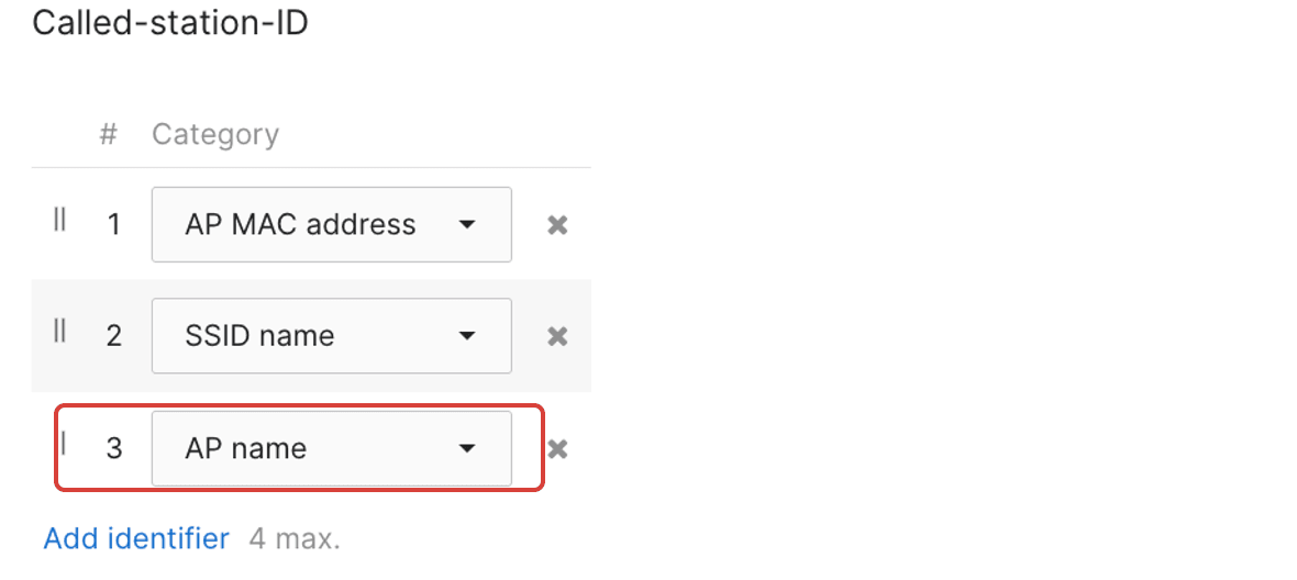
Add AP name to the Called-station-ID list (it is not there by default). -
Save and test
Save the Meraki Access Control page and connect a test device to the SSID. The Captive Portal should render and a login should appear on the Sign-In Dashboard after sign-in.
Everything above is what Sign In needs. The customer is free to configure the rest of the SSID (VLAN, bandwidth, IP assignment, scheduling, and so on) however they want their network to behave.
3b. MAB with a Managed Pre-Shared Key (optional)
Section titled “3b. MAB with a Managed Pre-Shared Key (optional)”When you want the SSID encrypted but still want MAC-based authentication through Netgraph, layer a Managed PSK on top of the MAB flow.
In the Netgraph admin
Section titled “In the Netgraph admin”The Setting Up Meraki with Pre-Shared Key and MAC-Based Access Control (optional) card appears below the main settings when Meraki Deployment Type is set to MAC-based Access Control.
-
Enter the Managed Pre-Shared Key
Type the PSK into Managed Pre-Shared Key (PSK). The field is masked by default; click the eye icon to reveal while typing.
-
Save
Click Update Managed Key. This PSK is what Meraki will provide to guests on the SSID.
In the Meraki Dashboard
Section titled “In the Meraki Dashboard”Follow the same steps as the plain MAB flow above, with one change:
- Security: select Identity PSK with RADIUS instead of MAC-based access control (no encryption). Mandatory DHCP stays on.
The rest — ISE Authentication splash, walled garden, RADIUS servers, Called-station-ID — is identical to the plain MAB flow.
3c. CoA — Splash Page via RADIUS Server
Section titled “3c. CoA — Splash Page via RADIUS Server”The CoA flow uses Meraki’s “Sign-on with my RADIUS server” splash option and a Custom Splash URL that points at Netgraph. The guest sees the Sign In Captive Portal rendered by Netgraph (rather than the ISE-style splash).
In the Netgraph admin
Section titled “In the Netgraph admin”-
Pick Splash Page via RADIUS Server
Under Meraki Basic Settings, pick Splash Page via RADIUS Server.
-
Pick the Meraki CoA setup
Under Meraki CoA setup, pick Only Meraki AP, Only Meraki MX, or Mixed Deployment (both AP and MX) — the Meraki-Dashboard steps shown below adjust to match.
-
Read the generated values
Note the values the card now shows: RADIUS servers and accounting servers, walled-garden domain, and the Custom Splash URL value.
In the Meraki Dashboard
Section titled “In the Meraki Dashboard”-
Sign-on with my RADIUS server
Under Wireless → Access control → Splash page, pick my RADIUS server from the Sign-on with dropdown.
-
Add RADIUS servers
Under Wireless → Access control → Radius, add the servers and accounting servers from the Netgraph admin. Set Enable data-carrier detect to DCD is disabled.
-
Enable the walled garden
Under Wireless → Access control → Walled Garden, add the walled-garden domain the Netgraph admin shows.
-
Custom Splash URL
Under Wireless → Splash Page → Custom Splash URL, paste in the Custom Splash URL value from Netgraph.
-
(Optional) Location and Scanning
Optional but recommended — see the next section.
Optional: Location and Scanning Integration (CoA only)
Section titled “Optional: Location and Scanning Integration (CoA only)”Meraki’s Location and Scanning Integration lets Netgraph see which clients are active on which SSID. It is configurable from the Meraki Location and Scanning Integration card on the same Settings page.
-
Turn on the toggle
Flip Enable Location and Scanning Integration on in the Netgraph admin.
-
Activate scanning in the Meraki Dashboard
Under Network-wide → General → Location and scanning, set Analytics to Analytics enabled and Scanning API to Scanning API enabled.
-
Exchange the Validator
Copy the Validator value from the Meraki Dashboard and paste it into Your Meraki Organisation Validator Key in the Netgraph admin.
-
Add a Post URL in Meraki
Back in the Meraki Dashboard, Add a Post URL with:
- POST URL — the value shown in the Netgraph admin.
- Secret — the scanning secret shown in the Netgraph admin (regeneratable from the button next to it).
- API Version — V3.
- Radio Type — Wifi.
-
Set the scanning SSID
Back in the Netgraph admin, enter the Guest Network Meraki SSID — clients are counted as online when they appear on this SSID.
-
Save in both places
Click Update Settings in the Netgraph admin and save the Meraki Dashboard page.
The Meraki Location and Scanning Integration Status card below reports the pipeline state — Waiting for first Meraki Cloud POST while Meraki hasn’t sent anything yet, OK once scanning data is flowing, Warning if posts stop.
4. Access Points
Section titled “4. Access Points”Under Service Integration → Meraki → Access Points, the admin shows the Meraki APs registered to this Sign-In Context, a trend chart of Registered Access Points and Access Point License counts, and a Batch Upload button for bulk onboarding.
The Meraki Access Point license registration card on the Settings page has an Enable automatic registration of Access Points toggle — when on, APs register (and claim a license) automatically as they appear. Turn it off to maintain the Access Points list manually.
Access Points are identified by MAC address. That MAC is also what Site-based redirects match on for CoA deployments — assign APs to a Site to steer guests to venue-specific landing pages.
Compared to Service Gateway
Section titled “Compared to Service Gateway”| Aspect | Cisco Meraki | Cisco Service Gateway |
|---|---|---|
| Hardware | None extra (Meraki APs already in place) | Cisco Catalyst / IOS-XE / SD-WAN router |
| Who hands out IPs | Meraki | The Netgraph cloud (DHCP relayed by the Service Gateway) |
| How the Captive Portal is reached | Meraki Custom Splash URL (CoA) or ISE splash page (MAB) | DHCP Option 114 / probe redirect via the Service Gateway |
| Deep-packet inspection | Not available | Available (Application Visibility) |
| Best for | Meraki-only venues | Venues standardised on Cisco routing |